archi-intelligence Research Series · Deep Dive 2026-10
Muscle and Nerve: High and Low Voltage in Automotive E/E Architecture
Data as of October 17, 2026
Contents
Abstract
Most discussion of automotive “high and low voltage” stops at a single number: 400 V or 800 V, 12 V or 48 V. This article argues that the number is the least important part.
We begin with a conceptual cleanup: high versus low voltage is first a shock-protection line (60 V DC), not a voltage value; “800 V” is an architecture class, not a reading. We then argue the core thesis: once compute centralizes and actuation goes by-wire, electricity stops being infrastructure for the E/E architecture and becomes part of the function itself. High voltage is the muscle and low voltage the nerve — and it is the nerve that wakes the muscle. A by-wire car with a full high-voltage battery and a dead low-voltage supply cannot turn its wheels with the steering wheel.
Two main theses follow. First, power is the fourth plane of the E/E architecture, alongside compute, network and software; a zonal architecture is only complete when power is zonal too, and the zonal controller is becoming an edge node that combines data, control and power. Second, distribution is not availability: an efficient 48 V zonal power network answers “how does the electricity get there”; autonomous driving asks “after a fault, is there still power, and for how long”. The second question requires an independence chain from energy source to actuator, and a number that today’s regulations and standards do not yet ask for — which we call the Minimum Energy to Safe State (MESS).
On top of this, the article distinguishes 800 V and 48 V as two different kinds of migration, discusses software-defined power and its physical limit, maps who leads which track, and describes the three governance regimes that have grown on the same 60 V physical boundary in Europe, China and the United States. The conclusion delivers three judgments and one warning, with six revision triggers.
Editorial note
This article is a Deep Dive, not a Working Paper. The line between the two is not length but level of commitment:
- Working Paper (D1–D4, Zenodo DOI) = locked claims. They cannot be silently revised and must withstand five years of citation.
- Deep Dive (this series) = disciplined observation. Revisable and refutable, explicitly marked as “what we see now”, outside the DOI system.
This article inherits the Working Papers’ epistemic discipline — source tiering, traceable evidence, mandatory counter-arguments and failure modes — but not their finality. It does not revise any published conclusion of D1–D4, nor does it change D2’s five-dimension scoring system or AR mapping; the D2 scores it cites are those of the published version. It does not score carmakers: power topology is among the least disclosed parts of a vehicle, and any score could only rest on inference. Evidence grades are marked in the text as [T1], [T2], [T3] and [inference]; see Appendix A. The concepts this article introduces and their definitions are in Appendix B. Its conclusions carry revision triggers (Chapter 10); if any is triggered, a revised version will be published with the changes marked.
Introduction: a fully charged car whose steering wheel will not turn the wheels
In the Cybertruck’s Instructions for Transporters, Tesla includes a reminder that few people notice: the Cybertruck uses steer-by-wire, and if the vehicle has no power, the steering wheel cannot turn the wheels [T1].
“No power” has a precise meaning here. The same manual goes on: if the Cybertruck has no low-voltage power, jump-start the low-voltage system first; and because it uses a 48 V low-voltage architecture, jump-starting from a source below 30 V (such as another vehicle or a 12 V portable jump starter) may leave some functions unavailable or degraded [T1]. In other words, the high-voltage battery may still hold over a hundred kilowatt-hours, but if that small 48 V, 4 Ah battery fails, the truck cannot be pushed, cannot be steered, and its doors will not open.
This is not a Tesla design flaw. It is the inevitable consequence of a physical fact in the by-wire era: high voltage is the car’s muscle, low voltage is its nerve — and it is the nerve that wakes the muscle.
This research series has come to this door three times without opening it. D2 listed “power” as one check item of redundancy depth within its functional-safety dimension (D4). Deep Dive 2026-08, The Driver Exits, wrote a contract for driverless operation, one clause of which reads: “if the main power supply fails, safety-critical loads must switch over seamlessly.” Deep Dive 2026-09, A System of Operating Systems, placed “power and network redundancy” in S0, the physical substrate of the vehicle control plane, and used Leapmotor’s “vehicle-wide 48 V” as an example of the co-evolution loop. All three mentioned electricity; none stopped to discuss it.
That is what this article does. It asks a single question:
Once compute centralizes and actuation goes by-wire, what does “electricity” turn from, and into, within the automotive E/E architecture?
Our answer compresses into four sentences, which also form the skeleton of the article:
High voltage is the muscle, low voltage the nerve; power is the fourth plane; distribution is not availability; what wins 48 V is the contract, not the voltage.
Expanded, they become six judgments:
- E1 | Definition: High versus low voltage is a safety line, not a voltage number; “400 V / 800 V / 1000 V” are architecture classes, not readings.
- E2 | The fourth plane: Power is a fourth plane, alongside compute, network and software. A zonal architecture is only complete when power is zonal too; the zonal controller is becoming an edge node that combines data, control and power.
- E3 | Two migrations: 400 V → 800 V is a vertical electrification migration; 12 V → 48 V is a horizontal E/E migration. The latter is technically simpler yet moves more slowly, because what it must rewrite is the interface of an entire supply chain.
- E4 | Availability: Distribution is not availability. By-wire actuation and autonomy at L3 and above turn the power topology into a functional-availability topology; the essence of redundancy is independence, not duplicated parts; and the last number of availability is energy.
- E5 | Software-defined power: Electricity is becoming an observable, controllable resource that can be allocated by scenario — but regulation requires the last gate to be physical.
- E6 | Tracks: There is no single “global high/low-voltage leader”, only leaders on different tracks; and the same physical boundary has grown three governance regimes in three regions.
We start with the most basic task: cleaning up the term “high and low voltage”.
1. The Naming Problem: high versus low voltage is a safety line, not a voltage number
1.1 A line drawn at 60 volts
“High voltage” and “low voltage” have a very specific regulatory definition in cars, and that definition has nothing to do with power. It is only about whether a person can be hurt by electricity.
UN Regulation No. 100 defines as high voltage any circuit whose working voltage is above 60 V DC and not above 1500 V, or above 30 V AC (rms) and not above 1000 V [T1]. ISO 6469-3 says the same thing in other words: below 60 V DC is voltage class A, which needs no protection against electric shock; above it is voltage class B [T1]. R100 also sets several hard limits: after a connector is opened, live parts must fall to a safe voltage within 1 second; DC bus insulation resistance must be at least 100 Ω/V, and AC at least 500 Ω/V [T1].
China’s mandatory standard GB 18384-2025, Electric Vehicles Safety Requirements, issued on December 31, 2025, replaces the 2020 edition and applies to newly submitted vehicle types from July 1, 2026; its drafting notes state explicitly that it aims to harmonize with UN R100, UN Global Technical Regulation GTR 20 and ISO 6469-3 [T1–T2]. On this line there is almost no disagreement worldwide. The disagreements lie above and below it, which Chapter 9 takes up.
The first corollary of this line is that 48 V is still low voltage. The whole reason it is cheap is that it is designed to stay below 60 V, so it needs no orange high-voltage cables, high-voltage interlock or insulation monitoring. But that premise carries an often-overlooked condition — including transients. If a 48 V network can stay above 60 V for any length of time, it slides into the high-voltage regime in the regulatory sense. That is why ISO 21780:2020 singles out 58–60 V as the “upper overvoltage range” and requires countermeasures (the standard was confirmed at systematic review on June 29, 2026 and remains current) [T1].
1.2 Three voltage worlds
“An 800 V car” and “a 48 V car” both suggest that the whole vehicle runs on one voltage. In fact a modern car contains at least three voltage worlds:
| Layer | Typical voltage | What it powers |
|---|---|---|
| High voltage (HV) | about 200–1000 V+ | traction, charging, high-power thermal management |
| Board net (LV backbone) | 12 / 24 / 48 V | controllers, sensors, actuators, steering and braking, body, central compute |
| Point of load (PoL) | 5 / 3.3 / 1.8 / 0.8 V… | inside chips and controllers |
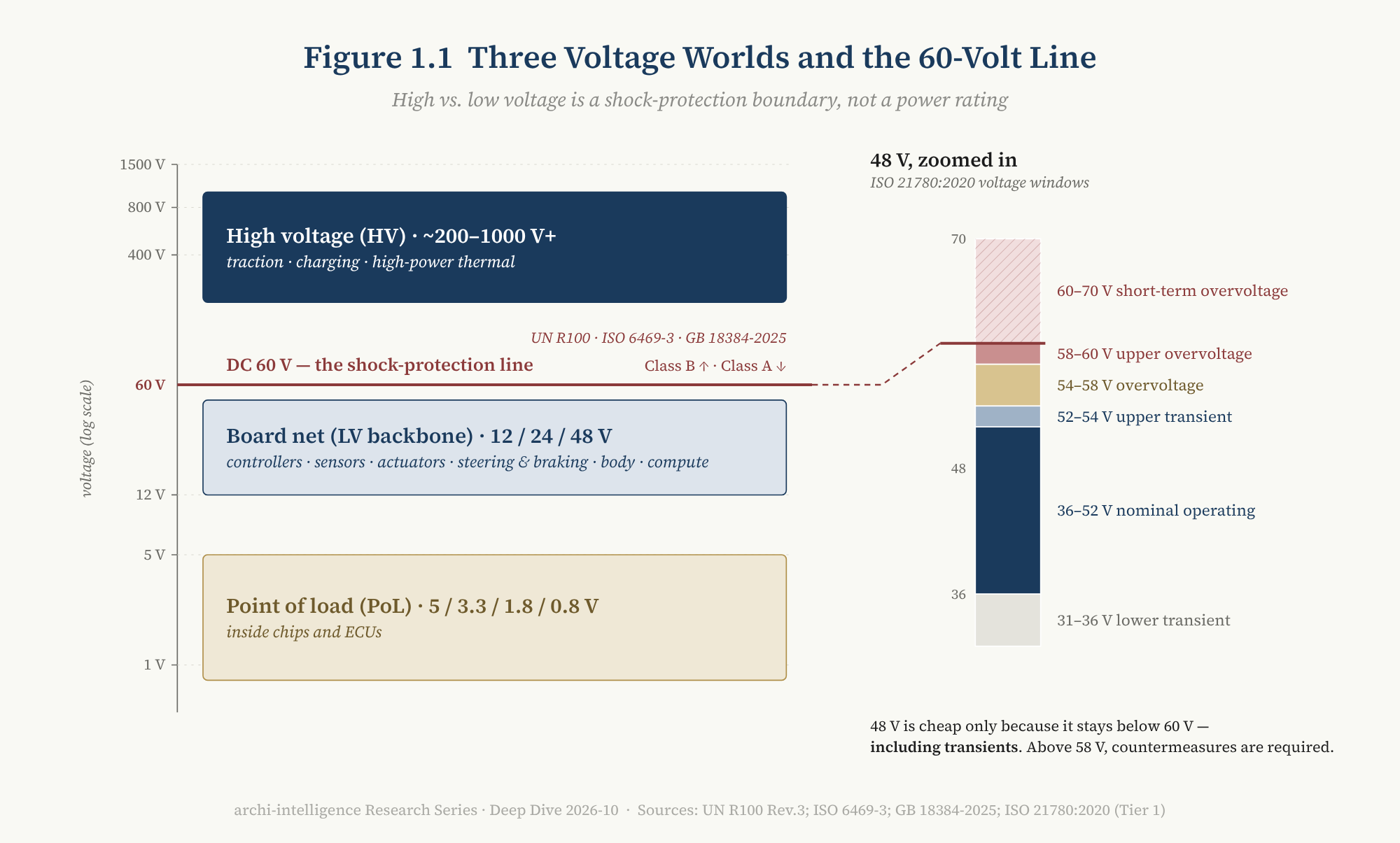
Figure 1.1 — Three voltage worlds and the 60-volt line. Reading note: the boundary between class A and class B is drawn at 60 V DC; the 48 V board net sits below the line, but its transient ceiling presses right against it.
So a “48 V car” means that the board-net backbone rises from 12 V to 48 V and is then stepped down inside zonal controllers and ECUs to 12 V and chip voltages — not that chips run directly on 48 V. This is the same logic as the data-center pattern of a “48 V rack bus → conversion close to the board”, an analogy Chapter 8 returns to.
1.3 “800 V” is not a reading
In marketing, “800 V” is a number. In engineering it can refer to at least six different quantities:
cell voltage → pack nominal voltage → pack operating window → DC bus voltage
       → maximum component working voltage → device blocking voltage (e.g. 1200 V SiC)
The Cybertruck is the best example. It is often classed as an “800 V architecture”, and Tesla itself uses that label, yet the specifications page of the official owner’s manual gives the high-voltage battery a nominal voltage of 700 V DC [T1]. The two are not in conflict: “800 V” is the voltage class to which device selection, insulation design and charging compatibility are engineered; 700 V is the nominal value.
Naming on the low-voltage side needs the same care. Tesla’s service manual calls the Cybertruck’s 48 V system a “mid voltage” (MV) architecture [T1]. This is a Tesla service term, meant to remind technicians that 48 V is more dangerous than conventional low voltage; in the ISO system, 48 V remains low voltage. Nor should it be confused with “medium voltage” in power engineering, which means kilovolts.
The consequence is methodological: any “league table” with a marketing voltage on its axis compares things that are not the same. When Chapter 7 compares carmakers’ approaches, it uses no voltage ranking. It asks a different question instead: how deep does this voltage class reach into the vehicle’s high-voltage domain (see 3.3)?
1.4 Summary
E1 | High versus low voltage is a safety line, not a voltage number. “400 V / 800 V / 1000 V” are architecture classes, not readings.
The definition looks like common sense, but it fixes the unit of analysis for the whole article. What we discuss is not “how high the voltage is”, but in what topology, and under what safety constraints, electricity reaches every place that needs it — and whether it still gets there when something goes wrong.
2. Muscle and Nerve
2.1 At runtime, high voltage feeds low voltage
In a battery-electric car driving normally, energy flows simply:
HV battery ──┬── inverter → motor (traction)
             ├── e-compressor / heater (thermal)
             └── HV→LV DC-DC → 12 V or 48 V board net
                                → zonal controllers / central compute / sensors / actuators
The most easily overlooked part of this chain is the DC-DC converter. In a combustion car, low-voltage power comes from an engine-driven alternator; in an electric car, the DC-DC is the alternator. Its failure modes — loss of output, output overvoltage — directly determine whether the entire low-voltage network can still work.
Put all powertrains side by side and a common migration appears:
| Powertrain | Class B high voltage? | Where low-voltage power comes from | Role of the LV battery |
|---|---|---|---|
| Combustion | No | engine-driven alternator | cranking + all permanent loads |
| 48 V mild hybrid | No (48 V is class A) | 48 V belt starter-generator → DC-DC | LV loads + cold-start backup |
| Hybrid / plug-in hybrid / range extender | Yes | HV→LV DC-DC | wake-up; the only supply before HV contactors close |
| Battery electric | Yes | HV→LV DC-DC (can step directly down to 48 V) | as above; can be replaced by lithium, supercapacitors or “in-pack” solutions |
Two additions. First, the plug-in hybrid is often the powertrain with the most complex energy architecture: it carries a mechanical energy chain, a high-voltage drive chain, a charging chain and a low-voltage electrical chain at once, with far more fault combinations than a pure EV [inference]. Second, from an E/E perspective a range extender is closer to “battery electric plus an on-board generator”: the engine does not drive the wheels. The supply chain already prices it this way — in February 2026 BorgWarner announced that it would supply an 800 V second-generation integrated drive module and a generator module with dual inverter for a major North American carmaker’s range-extended pickups and large SUVs, starting production in 2029 [T2, company claim].
2.2 At start-up, low voltage wakes high voltage
But wind the clock back to the moment the vehicle wakes, and the causality runs the other way:
LV battery → vehicle controller / battery management / safety controllers wake
          → HV interlock and insulation self-test → close main negative contactor → precharge
          → close main positive contactor → HV online → DC-DC starts → HV begins to feed LV
High-voltage contactors are only safe when open, and every controller needed to close them runs on low voltage. So a car with a full high-voltage battery and a drained low-voltage battery is completely “dead”. This is not a design error; it follows inevitably from the safety logic that the high-voltage system must stay isolated until the contactors close [inference, standard industry practice].
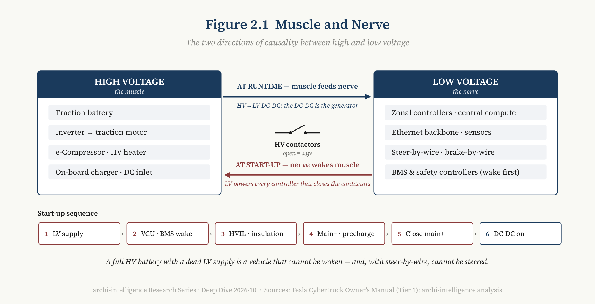
Figure 2.1 — Muscle and nerve. Reading note: at runtime the arrow points from high voltage to low voltage (DC-DC); at start-up it points from low voltage to high voltage (wake-up and contactor closing). Both directions must hold for the system to work.
2.3 After by-wire, the nerve is the lifeline
In the era of mechanical steering columns and hydraulic brakes, a low-voltage failure meant “body and infotainment functions degrade”: without steering assist, a person could still turn the wheel harder; without brake assist, a person could still press harder. A power fault was a reliability problem, not a question of whether the car could still be controlled.
By-wire changes that. The Cybertruck uses four-wheel steer-by-wire [T1], and its owner’s manual is clear about the 48 V battery’s role: when the high-voltage battery is unavailable, the 48 V battery powers low-voltage systems such as windows, doors and the touchscreen, while providing redundant power for critical systems such as power steering [T1]. The same documentation says that 48 V connectors are blue and 48 V wires are wrapped in blue tape; because the voltage is higher than conventional low voltage, live work carries higher risks of personal injury, arcing and component damage [T1].
Read together, the conclusion is: in the by-wire era, the low-voltage network has itself become a driving-safety system. A 12 V failure used to mean “inconvenient”; now it can mean the simultaneous loss of steering, braking, automated-driving compute, Ethernet switches and zonal controllers [inference].
2.4 Removing the “small battery” does not remove the LV energy-storage domain
At its technology day on September 16, 2026, Leapmotor launched its “CTC 3.0 HV–LV fused battery”: the separate low-voltage battery is eliminated and a low-voltage module is integrated into the high-voltage pack, managed by the main battery; the company says low-voltage capacity rises sevenfold, users avoid the cost of replacing a low-voltage battery, the related patents are being opened to the industry, and new models will use it from 2027 [T2, company claim].
For the user this is a relief: lead-acid batteries are heavy, short-lived and need periodic replacement. For the architecture it needs a more precise description — it removes a separate part, not the low-voltage energy-storage function. The start-up chain of 2.2 still holds: some energy must still be able to power the controllers while the high-voltage contactors are open. What changes is the packaging boundary of that energy: from a separate battery into the housing of the high-voltage pack.
Once the packaging boundary moves, several new questions follow [inference]:
- Common-cause failure: could one underbody impact or one thermal event take out both the main energy source and the wake-up energy?
- Post-crash availability: after a collision, what powers door opening, hazard lights and emergency calls?
- Repair and rescue: if the low-voltage module fails, does the pack have to come out? Media have already raised this, arguing that repair labor could rise noticeably [T3].
These questions have no standard answers, and Leapmotor may well have answered them in its design (public sources do not say). But they show clearly the distinction Chapter 6 develops: “this battery has been removed” is a distribution question; “is there still power after something goes wrong” is an availability question.
2.5 Summary
High voltage is the muscle, low voltage the nerve. At runtime the muscle feeds the nerve; at start-up the nerve wakes the muscle. When mechanical backups existed, damage to the nerve only made the car harder to drive; in the by-wire era, damage to the nerve means the car cannot be controlled.
This is why electricity can no longer be treated as the background of the E/E architecture. But before turning to the fourth plane, one more common confusion needs to be taken apart: are 800 V and 48 V the same kind of migration?
3. Two Migration Curves
3.1 One formula, two discounts
Every argument for raising voltage comes from the same pair of formulas: power equals voltage times current, and conductor loss equals current squared times resistance. At the same power, higher voltage means lower current:
| Voltage step | Current at same power | Conductor loss at same resistance |
|---|---|---|
| 12 V → 48 V | falls to 1/4 | falls to 1/16 |
| 400 V → 800 V | falls to 1/2 | falls to 1/4 |
| 800 V → 1000 V | falls to 0.8 | falls to 0.64 |
But the third column carries a premise: constant resistance. In practice engineers use the lower current to make conductors thinner, so resistance rises. Aptiv’s 48 V white paper says so plainly: losses can “in theory” fall to one-sixteenth, but as wire gauge shrinks resistance increases, and the actual loss depends on system optimization [T2].
A clarification of the previous article in this series belongs here. In discussing Leapmotor LEAP 5.0, Deep Dive 2026-09 quoted Leapmotor’s official claim that “harness heat loss falls to 1/16 of the original” [T2–T3]. That figure is the theoretical value at constant resistance. In practice a large part of the gain from higher voltage is cashed in as thinner, lighter, cheaper harnesses, terminals and connectors, not as a sixteenfold loss reduction. This article does not revise the September piece: its wording there was “the company says”, which still stands as a report of the company’s claim; what this section adds is the physical premise behind the number.
3.2 Voltage is not a league table
On the high-voltage side, the production timeline of the past seven years looks roughly like this:
- Porsche Taycan (2019) was the starting point of 800 V in series production, justified by halved current at the same power, smaller and lighter conductors, and higher DC fast-charging capability [T1–T2].
- Hyundai E-GMP innovated not in 800 V itself but in compatibility: it reuses the rear motor and inverter to raise the voltage of a 400 V charger to 800 V, without a separate large boost converter [T1].
- Lucid Gravity reaches a system voltage of 926 V, also boosting with the motor windings as the inductor [T2].
- NIO ET9 claims “full-domain 900 V”, with a maximum system voltage of 925 V, peak charging power of 600 kW, peak current of 765 A and in-house 1200 V silicon-carbide modules [T1–T2].
- BYD Super e-Platform (March 2025) claims “full-domain 1000 V”, with 1000 A and 1000 kW peak charging [T2, company claim].
Reading this timeline as “higher and higher, more and more advanced” is a mistake. Each step up in voltage raises the cost of every one of the following: device blocking voltage, insulation coordination, creepage and clearance, partial discharge, contactors and fuses, connectors, motor winding insulation, bearing currents, electromagnetic compatibility and switching speed, service and rescue safety, crash isolation, compatibility with lower-voltage chargers, and the thermal and auxiliary supply chain. Returns diminish while costs rise. The optimal voltage is an architecture trade-off, not a higher-is-better metric.
3.3 Full-domain HV penetration
So when comparing two carmakers’ high-voltage architectures, what should be compared?
This article proposes a measure: full-domain HV penetration — how many components in the vehicle’s high-voltage domain natively run at that voltage class, and how many still need conversion.
The question matters because an “800 V car” can be built in two completely different ways:
Implementation A: 800 V battery, 800 V motor and inverter,
                  but e-compressor, heater, DC-DC and on-board charger still at 400 V, bridged by conversion.
Implementation B: every high-voltage component above runs natively at 800 V.
The two share a marketing voltage, but their system complexity, conversion losses and supply-chain requirements are entirely different. BYD and NIO both use the word “full-domain” in their messaging: BYD says the battery, motor, power electronics and air conditioning all move into the 1000 V class [T2, company claim]; NIO says its 900 V system supplies the drive, battery, controllers, DC-DC and other components [T1–T2]. The word “full-domain” is itself a signal: the industry has realized that battery voltage is not the vehicle’s high-voltage architecture.
[inference] Full-domain HV penetration cannot yet be measured precisely from public sources — no carmaker has published a “share of native 800 V components”. This article offers it as a way of asking, not a score: the next time you see a voltage number, first ask how far it reaches.
3.4 Four engineering realities of 48 V
On the low-voltage side, 48 V brings not only thinner wires but a set of engineering problems that did not exist at 12 V. Aptiv’s white paper lists four [T2]:
- Arcing. A small arc when a 12 V circuit opens usually extinguishes itself; a 48 V arc can persist and destroy terminals and connectors. Terminals need more spacing, hot plugging must be avoided, and terminal back-out and fretting corrosion need watching.
- Electrochemical corrosion. If a connector is accidentally exposed to an electrolyte such as salt water, 48 V corrodes terminals far more aggressively than 12 V, raising sealing requirements.
- Mixed-voltage isolation. 48 V and 12 V should preferably not share a connector; where unavoidable, they must be physically separated. Nor should they share a ground stud — if the stud loosens, current can flow from a 48 V device into a 12 V device through the common ground.
- Creepage and clearance. Design to IEC 60664-1, and protect for 60 V, not 48 V. Most conventional connectors meet clearance requirements, but creepage distances may need redesign.
ISO 21780 defines a set of voltage windows for 48 V: 36–52 V is the nominal operating range, 52–54 V the upper transient range, 54–58 V overvoltage, 58–60 V upper overvoltage, and short-term overvoltage up to 70 V [T1]. These windows were born in the context of 48 V mild hybrids, which must withstand overvoltage from the starter-generator’s energy recovery. The 48 V net in a battery-electric car is generated from high voltage through a DC-DC and has no starter-generator, so in principle the window could be narrower — but as of this article’s data date, no such “EV-specific window” has been standardized [inference].
3.5 Vertical migration and horizontal migration
Look at the high-voltage and low-voltage upgrades together, and they turn out to be two migrations of entirely different kinds.
| 400 V → 800 V → 1000 V | 12 V → 48 V | |
|---|---|---|
| Direction | Vertical: along the drive and charging chain | Horizontal: across the whole vehicle |
| Objects involved | dozens of high-power components: battery, inverter, motor, on-board charger, DC-DC, compressor, HV distribution box, connectors | hundreds of endpoints: controllers, motors, actuators, lamps, pumps, fans, door locks, connectors, fuses and switches — and the decades of 12 V supplier interfaces behind them |
| Main difficulty | devices, insulation, cost | organization and ecosystem: whether suppliers will develop 48 V parts for a market that has not yet reached scale |
| Architecture it belongs to | electrification architecture | E/E architecture |
This explains an apparent paradox: 48 V is far less technically difficult than 800 V, yet it moves much more slowly. 800 V needs a few dozen high-power component suppliers to upgrade in step; 48 V needs an entire supply chain — including the tier-2 and tier-3 suppliers who make window motors, door locks and reading lamps — to change interfaces at the same time. This is not an engineering problem but a coordination problem of “who moves first” [inference].
3.6 Three LV routes, and a battle over interfaces
In 2026 the low-voltage world shows three routes [inference: the route classification is this article’s analytical framework]:
Route 1: a 48 V backbone, switching the whole vehicle.
- Tesla: The Cybertruck (deliveries from 2023) was the first production vehicle with a vehicle-wide 48 V system. In October 2024 Tesla published its “Low-Voltage Connector Standard” (LVCS): building on the Cybertruck’s 48 V architecture, it cuts the number of connector types on the vehicle to six, covering more than 90% of devices, uses the industry’s common light blue, and openly invites all parts suppliers and carmakers to join [T1].
- Ford: The mid-size electric pickup on the UEV platform, starting production in 2027, will use 48 V, stepped down directly from the 400 V battery through a DC-DC; Ford calls it its first 48 V low-voltage system [T1–T2].
- Chery × Bosch: On April 24, 2026, at the Beijing auto show, the two signed a framework agreement for joint development and series production of a vehicle-wide 48 V architecture, launching with the Exeed brand. They say vehicle power supply capacity rises to 15 kW (versus about 3–4 kW for mainstream 12 V systems), the system weighs over 10 kg less, steer-by-wire motor response improves by more than 20%, and the design uses independent redundant power supply [T2, company claim].
- Leapmotor LEAP 5.0: The “Four-Leaf Clover 5.0” central domain-controller architecture uses vehicle-wide 48 V and vehicle-wide Ethernet, with “the remaining domain controllers only executing”, a vehicle harness of about 500 meters, and first models in production in 2027 [T2, company claim].
- Hyundai: is reportedly asking suppliers to develop end-to-end 48 V parts for all its models and for its robotics business, and has chosen not to adopt Tesla’s scheme in order to protect its own supplier base [T3].
Route 2: choosing voltage by load.
- NIO ET9 supports both 12 V and 48 V: the vehicle has two 12 V systems and one 48 V system, with 48 V dedicated to high-power loads such as the fully active suspension [T2].
- Li Auto L9 Livis goes further: its active suspension sits directly on 800 V, on the grounds that the power 48 V can deliver is relatively small [T2, company claim].
Route 3: low voltage into the pack.
- Leapmotor CTC 3.0 integrates low-voltage storage into the high-voltage pack (see 2.4). It can be combined with Route 1: Leapmotor’s next-generation platform is both vehicle-wide 48 V and HV–LV fused.
This article’s judgment: the 12 V → 48 V migration is turning into a battle over interfaces in the physical world. Deep Dive 2026-09 argued that at the software level, what the industry is actually standardizing is not “one automotive OS” but vehicle APIs and runtime contracts. The same thing is happening on the low-voltage network: what determines the speed of the migration is not the number 48 but who sets the “physical contracts” — connector form factors, voltage windows, isolation rules, color coding.
Tesla’s LVCS is one public draft contract; the Chery–Bosch deal is another, between a European tier-1 and a Chinese carmaker; Hyundai has chosen to write its own; and ISO 21780 is still stuck at the windows of the mild-hybrid era. [inference] Whichever contract enough suppliers adopt will set the cost curve of 48 V. What wins 48 V is the contract, not the voltage.
E3 | 400 V → 800 V is a vertical electrification migration; 12 V → 48 V is a horizontal E/E migration. The latter is technically simpler yet moves more slowly, because what it must rewrite is the interface of an entire supply chain.
4. The Fourth Plane
4.1 Why E/E architecture diagrams never draw electricity
Open any carmaker’s E/E architecture diagram from the past twenty years and you will see controllers, buses, gateways and function allocation, but rarely a power path. Electricity usually appears on the diagram as a single label: “12 V”.
There were historical reasons for this [inference]:
- First, everything ran on the same electricity. In a uniform 12 V world, “this controller is also on 12 V” distinguishes nothing; which CAN bus it hangs on and which domain it belongs to are what the architect cares about.
- Second, organizations separated signals from power. The traditional division of labor at carmakers roughly runs: the E/E architecture team owns controllers, functions and networks; the harness and power distribution team (often called Bordnetz in German) owns wires, fuses, relays and connectors; the powertrain team owns the battery, alternator and starter. The same vehicle can have a very mature function and network model, yet no equally mature end-to-end model of power dependencies.
- Third, the core controls still had mechanical backups. Steering had a steering column, braking had hydraulics. A power failure did not mean loss of control, so electricity was infrastructure rather than part of the function.
All three premises are disappearing at once: 48 V breaks “the same electricity”, zonal architecture breaks the organizational split, and by-wire breaks the mechanical backup.
4.2 Four planes
This article proposes a descriptive frame: the next generation of automotive E/E architecture needs at least four planes to describe it.
| Plane | The question it answers | Typical objects |
|---|---|---|
| Compute plane | who computes, and where functions are deployed | central compute, zonal controllers, safety microcontrollers |
| Network plane | how data flows | Ethernet / time-sensitive networking, CAN, high-speed serial links |
| Power plane | how energy is distributed, converted and isolated, and how it is reconfigured after a fault | high voltage / 48 V / 12 V, DC-DC, distribution, electronic fuses, primary and backup supply paths |
| Software plane | who orchestrates these resources and manages their lifecycle | vehicle control plane (contract + orchestration + lifecycle) |
Functional safety, cybersecurity and diagnostics cut across all four planes.
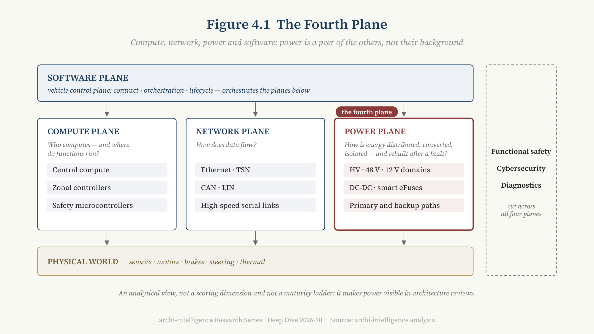
Figure 4.1 — The fourth plane: compute, network, power, software. Reading note: the power plane is not an appendage of compute or network but a peer layer beside them; the software plane orchestrates all of them from above; functional safety runs through everything.
E2 | Power is a fourth plane, alongside compute, network and software.
Its relationship to this series’ existing frameworks needs stating clearly. In Deep Dive 2026-09’s six-layer stack model, “power and network redundancy” belongs to S0 (the E/E physical substrate); in D2’s five-dimension scoring, “power” is one check item of redundancy depth within the functional-safety dimension (D4). The fourth plane does not revise either of these; it pulls out the part previously buried in S0 and D4 so that it can be seen on its own. It is an analytical view, not a new scoring dimension, and not a maturity ladder.
4.3 Only half zonal
The core idea of zonal architecture is to organize controllers by physical location rather than by function: sensors and actuators at the front connect to the front zonal controller, those at the rear to the rear one, and the zonal controllers connect to central compute over a high-speed backbone.
Applied only to data, this idea is only half done. Imagine a car whose network has become “central compute + Ethernet backbone + front and rear zonal controllers”, but whose power still comes from one central fuse box running long supply lines to the front, the rear, the doors and the cabin — the heaviest and longest part of the harness is exactly the part that has not been zoned [inference].
Zoning is complete when power is organized by zone too — distribution, voltage conversion and fault isolation arranged by physical zone and handled by the zonal controller. This article calls that Power-Zonal. In 2025–2026 it began to appear in production vehicles:
- BMW Neue Klasse: the zonal harness divides the vehicle into four zones — front, center, rear and roof — using 600 meters less wire than the previous generation and weighing 30% less; within each zone the zonal controller handles data, and smart eFuses replace up to 150 conventional fuses [T1].
- NIO ET9: functional domain controllers are eliminated, leaving only front and rear zonal controllers carrying all sensors and actuators; a high-performance Ethernet ring controls all vehicle functions including steer-by-wire; the low-voltage supply uses dual-redundant power, every electrical load is electronically controlled, and the car has about 100 electronic fuses [T2].
- Ford UEV: five main zonal modules plus 48 V; the harness is 4,000 feet shorter and 22 pounds lighter than the Mustang Mach-E’s [T1–T2, company claim].
- Leapmotor Four-Leaf Clover 5.0: central integrated control, “the remaining domain controllers only executing”, vehicle-wide 48 V, a harness of about 500 meters [T2, company claim].
The supply chain is turning this into standard parts as well. Texas Instruments’ 48 V zonal reference design TIDA-020094, updated in April 2026, integrates the 48 V backbone, 48 V → 12 V conversion, high-side switches and smart eFuses, and motor drives into a zonal module, and supports chaining several zonal modules for system-level evaluation [T2].
4.4 The zonal controller: an edge node for data, control and power
Put these together and the zonal controller’s role has changed:
| Capability | Traditional controller / gateway | New-generation zonal controller |
|---|---|---|
| Bus gateway (CAN / LIN / Ethernet) | yes | yes |
| I/O aggregation | partly | yes |
| Load drivers | spread across controllers | concentrated in the zone |
| Power distribution | external fuse box | moves into the zonal controller |
| Smart eFuses | rare | standard |
| 48 V → 12 V conversion | external | can be done within the zone |
| Fault isolation | mainly network | network + power |
A more accurate description is: zonal controller = data edge + control edge + power edge.
There is a contrast here worth pausing on. Deep Dive 2026-09 discussed the “dumbing-down spectrum” of zonal controllers: GM’s zonal “aggregators” only forward data and commands and do not execute control logic [T1]. Looking only at the compute plane, the zonal controller is getting “dumber”. But on the power plane it is getting “heavier”: power distribution, electronic fuses, voltage conversion and fault isolation are all moving into the zone. [inference] The zonal controller is getting thinner in logic and thicker in power. This is the same structure as September’s judgment about the operating system in the AI era — thinner on top, thicker at the base: intelligence moves to the center, physical interfaces move to the edge.
Intelligence centralizes; physical interfacing decentralizes.
Counting controllers alone, it is easy to misjudge a “centralized architecture”. Compute is centralizing, while I/O, actuation and power distribution are moving closer to physical locations.
4.5 12 V will not disappear; it becomes a local compatibility rail
The end state of a 48 V zonal architecture is unlikely to be “12 V gone overnight”. A more likely shape is [inference]:
                    48 V backbone
          ┌────────────┼────────────┐
     front zone      center zone     rear zone
          │            │            │
   48 V heavy loads  48 V heavy loads  48 V heavy loads
   12 V compat rail  12 V compat rail  12 V compat rail (DC-DC inside the zone)
High-power loads (steering, braking, active suspension, pumps, fans, heaters) run directly on 48 V; hundreds of small loads stay on 12 V, converted close by in the zonal controller. 12 V retreats from vehicle backbone to a local compatibility rail. This is also why even the Cybertruck still carries several internal power rails from about 5 V to 48 V [T3].
4.6 Summary
The fourth plane is not a figure of speech. What it means can be tested: to judge how far a vehicle’s zoning has gone, do not ask only “how many zonal controllers does it have”, but ask five questions —
- Is data zoned?
- Is I/O zoned?
- Is power distribution zoned?
- Is fault isolation zoned?
- After something goes wrong, are the energy sources of each zone independent of one another?
The industry has been answering the first two for years. The last three are the real dividing line in 2026. And the fifth leads to this article’s second main thesis — but first, another thing is happening on the power plane: electricity has started to take orders from software.
5. Software-Defined Power
5.1 The fuse becomes a program
A traditional fuse works passively: too much current, it blows, you replace it. It does not know why it blew and tells no one.
Smart eFuses and semiconductor switches change this. They can measure current and temperature continuously, judge overload with a model rather than a fusible link, open on a software command, locate and report the fault, recover when conditions allow, and shed loads selectively by priority. For the first time, electricity becomes an observable, controllable resource.
This article calls the shift software-defined power. The term is already in use in data centers; this article defines it in the automotive E/E context: the allocation, protection and priority of electric power are decided dynamically by software according to vehicle state, rather than fixed once by hardware at design time.
Production evidence has appeared. BMW Neue Klasse’s “smart power modes” switch off unneeded consumers according to the vehicle’s state — driving, parked, charging, updating — and BMW cites a 20% efficiency gain from this [T1, company claim]. NIO ET9’s low-voltage system electronically controls every electrical load [T2].
5.2 Power becomes an actuator of network management
Once electricity can be controlled by software, it becomes bound up with network management [inference].
In a traditional architecture, a controller “sleeping” means its microcontroller enters a low-power mode; it still sits on permanent power and still draws quiescent current. In a software-defined power architecture, sleeping can mean the zonal controller cuts its supply outright. Power distribution becomes an actuator of network management.
This creates a new set of arbitration problems: remote wake-ups (from the telematics unit), timed wake-ups (battery balancing, the DC-DC topping up the low-voltage battery) and charging wake-ups (a plug inserted) all compete for resources across “low-voltage charge, quiescent-current budget and security policy”. Ethernet’s standby power and wake-up latency are both higher than CAN’s, which is why many zonal architectures still keep CAN or LIN as the channel for wake-up and safety fallback.
5.3 OTA has to do the energy sums first
Over-the-air updates (OTA) are another place the power plane gets drawn into [inference].
In an electric car, an OTA update can be powered in two ways: either from the low-voltage battery alone, constrained by charge and duration; or by putting the vehicle into a dedicated state of “high voltage closed but not drivable”, with the DC-DC supplying power continuously. The second raises an engineering paradox: when the component being flashed is the battery management system, the controller of the high-voltage distribution box, or the DC-DC itself, the component powering the vehicle is the component being updated.
So a mature OTA orchestrator must be able to read the energy budget and issue commands to the power state machine. Deep Dive 2026-09 argued that OTA granularity is a proxy for the coverage of the vehicle control plane; on the power plane one can add: which domain you can update depends on which domain you can guarantee to power during the update.
5.4 Control-plane orchestration extends from compute to power
Put 5.1 to 5.3 together and we return to September’s framework. Deep Dive 2026-09 broke the vehicle control plane into three parts: contract, orchestration and lifecycle. “Orchestration” meant mixed-criticality scheduling, proof of isolation, function migration and resource arbitration — and the resource under discussion then was mainly compute.
Software-defining the power plane means the object of orchestration extends from compute to power.
The scenario that shows this best is load shedding after a fault. A reasonable priority order looks roughly like this [inference]:
| Tier | Loads | When power is short |
|---|---|---|
| S · Safety control | steering, braking, critical compute, critical network | given up last |
| A · Perception and localization | key cameras, radar, lidar, positioning and inertial navigation | kept as long as possible |
| B · Operational support | cooling pumps and thermal management needed for safe operation | kept as needed |
| C · Visibility and rescue | hazard lights, exterior lighting, emergency call, door unlocking | critical parts kept |
| D · Comfort | comfort climate, seats, infotainment, non-critical lighting | shed first |
This table is not decided by hardware; it is executed by software at the moment the fault occurs. It is the same problem September discussed — “how ASIL D braking and QM-level music playback share one chip” — projected onto two planes: compute must be isolated by criticality, and power must be allocated by criticality.
5.5 The last gate is physical
Software-defined power has a limit, and regulation draws it.
Once GB 18384-2025 took effect on July 1, 2026, one widely reported requirement is that vehicles must carry an independent physical one-touch power cut-off, replacing earlier software-controlled shut-off; a driver or rescuer can cut the vehicle’s entire high-voltage circuit with a single action [T2]. The same standard requires that after a high-voltage service disconnect is opened, live parts fall to a safe voltage within 1 second, and that after a low-voltage service disconnect is opened, class B circuits fall to a safe voltage within 10 seconds [T2].
[inference] This requirement does not contradict the trend toward software-defined power; it precisely draws software’s boundary: software can manage the power plane, but the last gate must be physical. This is the same structure as Deep Dive 2026-09’s judgment on AI entering the operating system — probabilistic intelligence must run inside deterministic governance. On the power plane, “deterministic governance” takes a form harder than code: a switch a person can reach out and pull.
E5 | Electricity is becoming an observable, controllable resource that can be allocated by scenario; but regulation requires the last gate to be physical.
5.6 The co-evolution loop on the power plane
Finally, the core thesis of Deep Dive 2026-09 — once functions become software, software workloads begin to design the next E/E architecture in reverse — holds on the power plane too [inference]:
- Only after Leapmotor concentrated control logic in the center, with “the remaining domain controllers only executing”, could distribution and wiring be reorganized as “one brain + several zones”, making 48 V and a 500-meter harness possible.
- BMW’s smart power modes need software that can switch loads off one by one, which requires programmable eFuses in the zonal controller rather than a row of fuses.
- Tesla lists “supporting reliable autonomy” among the design goals of its 48 V connector standard [T1]: it is the autonomy workload that is defining the interfaces of the low-voltage network in reverse.
First comes what the software needs to do; then comes how the electricity is laid. The lower half of the co-evolution loop has started to turn on the power plane too.
6. From Reliable Supply to Provable Availability
6.1 Division of labor with The Driver Exits
Deep Dive 2026-08, The Driver Exits, wrote a contract for driverless operation. Its “full-chain redundancy” clause reads: braking, steering, power and communication — every path to the physical world must have a second one; if the main power supply fails, safety-critical loads must switch over seamlessly. That article discussed why the contract must be signed, and how it reprices carmakers, disciplines and the value chain.
This chapter does only something narrower: it unpacks the “power” clause of the contract — what it means in engineering terms, how it most commonly fails, and which number it is still missing.
First, a common misunderstanding. SAE J3016 was reissued in 2026 with its level definitions unchanged: L3 drives itself under limited conditions and requires a human to take over after a warning or an evident failure; L4 drives itself under limited conditions without needing a human to resolve risk [T1]. J3016 is a taxonomy; it prescribes no voltage and no power topology. L3 does not inherently require two batteries, and L4 does not inherently require 48 V. What really changes is who is the fallback: from L2 to L3 to L4, fallback responsibility moves from the human to the system, and the power requirements are derived from that transfer of responsibility [inference].
6.2 Distribution is not availability
The previous two chapters were about distribution: how electricity gets there, how efficiently, lightly and flexibly. Autonomous driving asks a different question: after a fault, do the critical nodes still have power, and for how long?
This article separates the two explicitly:
| Distribution architecture | Availability architecture | |
|---|---|---|
| Question it answers | how electricity gets there | after a fault, is there still power, and for how long |
| Objects | voltage domains, DC-DC, distribution boxes, eFuses, wires, connectors, zonal distribution | energy redundancy, conversion redundancy, primary and backup supply paths, backup storage, independence, common-cause failure, fault isolation, wake-up, the energy budget of the minimal risk manoeuvre |
| Optimization goal | efficiency, weight, cost, harness length | resilience, provability |
E4 | Distribution is not availability.
The two can be completely decoupled [inference]. A car can have a very advanced 48 V zonal distribution — an extremely short harness, very high efficiency — and still have one energy source, one DC-DC and one bus: efficient, but not fail-operational. Conversely, a conventional 12 V L3 car may be heavy with a long harness, yet have two batteries and two independent supply paths: not efficient, but highly available.
Efficiency is not resilience. In D2, this series observed that “functional-safety certification decouples from architecture maturity” — European carmakers lead on functional safety and lag on centralization. On the power plane the same decoupling appears in another form: how advanced distribution is and how strong availability is are two independent axes.
6.3 The independence chain
So what guarantees availability? The usual answer is “redundancy”. But the word is often misread as “doubling the number of parts”.
This article breaks power redundancy into a six-layer independence chain [inference, combining ISO 26262’s methods for independence and common-cause failure analysis]:
| Layer | Content | The question to answer |
|---|---|---|
| 1 Energy | main HV battery, backup LV storage, independent partitions inside the pack | could one collision, thermal event or contactor fault take out both main and backup energy? |
| 2 Conversion | two DC-DCs, or a DC-DC plus independent storage | do the two buses ultimately share one DC-DC? |
| 3 Distribution | A/B buses, separate fuses and eFuses, separated routing, grounding | do the two paths share a fuse, a connector housing, a ground point or the same harness channel? |
| 4 Compute and network | A/B compute units, A/B switches | do the A/B networks share a switch, or the power supply of the same zonal controller? |
| 5 Actuation | dual-winding steering motor, dual controllers, independent braking paths | can the last physical action still happen? |
| 6 Energy management | remaining-energy monitoring, load shedding, minimal-risk-manoeuvre budget | how much energy is left, and is it enough to bring the car to a safe state? |
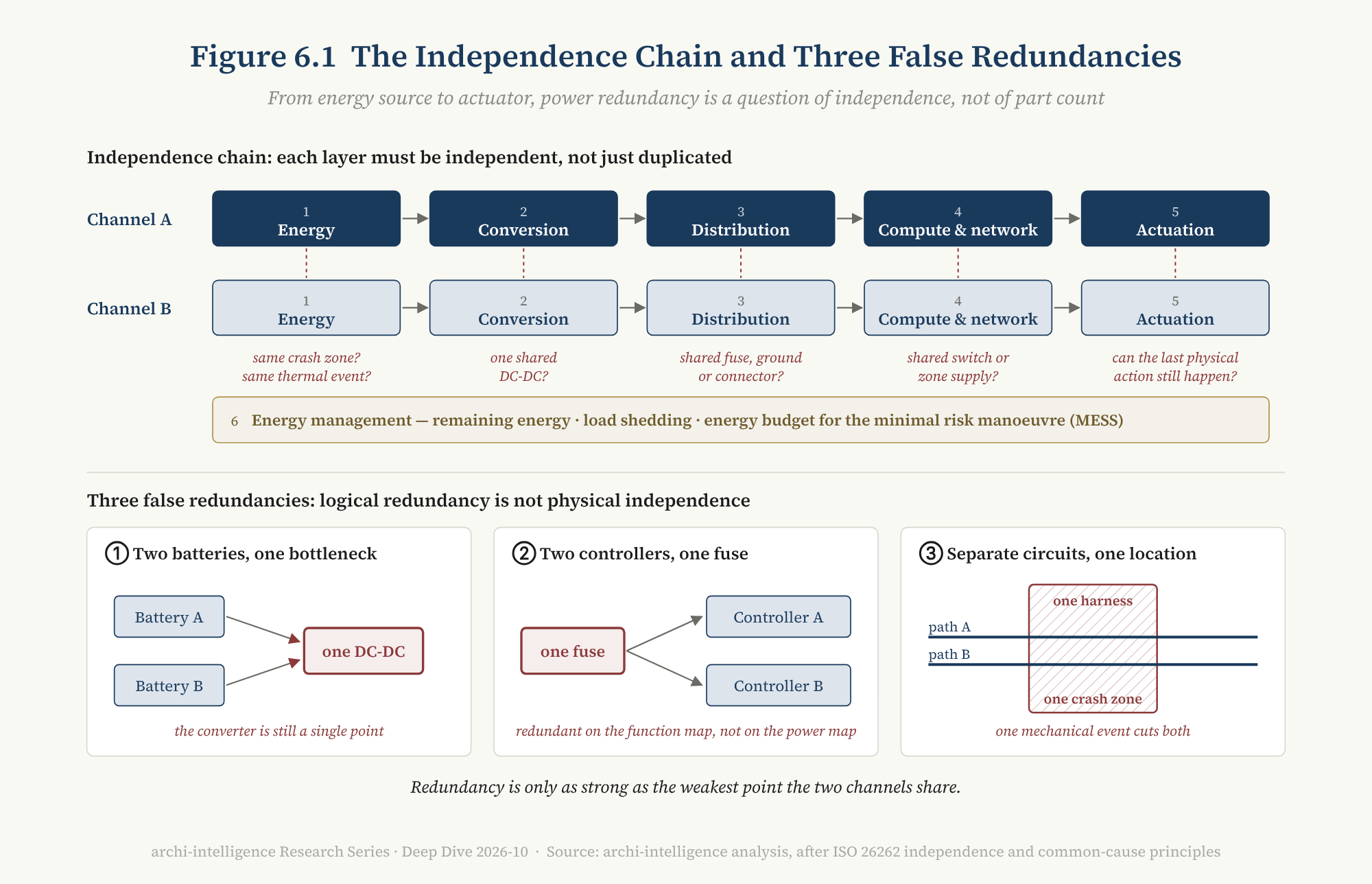
Figure 6.1 — The independence chain and three false redundancies. Reading note: the upper half is an A/B dual channel running from energy source to actuator; the lower half shows three counter-examples that “look redundant but share a common cause”. The strength of redundancy is set by the weakest shared point on the chain.
ISO 26262’s requirements here can be summed up as three questions: are the paths physically independent? Can a fault be isolated rather than propagated to the other path? Does the backup actually work — which requires periodic self-tests, otherwise a latent fault can make the backup fail at exactly the moment it is needed [inference, standard industry practice].
6.4 Three false redundancies
The most common failure of redundancy is not “no backup” but “the backup shares something with the main path” [inference]:
False redundancy 1: two batteries, one bottleneck. Two batteries feed into the same DC-DC or the same distribution box — the bottleneck is still a single point.
False redundancy 2: two controllers, one fuse. The function diagram shows compute units A and B; on the power diagram they hang behind the same fuse.
False redundancy 3: electrically independent, physically co-located. Two supply paths are completely independent on the circuit diagram, yet run through the same harness channel, the same crash zone, or the same connector housing. One mechanical event cuts both.
The three examples share one trait: they only show up when the function diagram and the power diagram are laid on top of each other. That is the practical meaning of Chapter 4’s “fourth plane” — if the power plane does not enter the architecture view, these common-cause failures are invisible in architecture reviews.
Logical redundancy is not physical independence.
6.5 Public evidence: who has said what
Power topology is among the least disclosed parts of a vehicle. The following lists only what can be confirmed from public sources, with a necessary warning: differences in public disclosure are not differences in capability.
Mercedes-Benz DRIVE PILOT (L3). This is the clearest public example. Mercedes says the four cores of its redundant architecture are braking, steering, power supply and some sensors; the battery, steering motor, wheel-speed sensors and data-computing algorithms are duplicated [T1–T2]; its US press release says the vehicle has redundant steering and braking actuators and a redundant on-board electrical system [T1–T2]. The safety assessment it submitted to US regulators lists the scope of redundancy as perception, compute, steering, braking, power supply and in-vehicle communication, with the functional-safety analysis aiming at fail-operational behavior under electronic faults [T1].
Waymo (L4). Waymo’s safety framework, published in 2020, lists at the hardware level backup steering and control actuators, and a backup computer and backup power within the compute platform [T1]. It has not published its specific power topology.
Tesla Cybertruck. The 48 V battery provides redundant power for critical systems such as power steering (see 2.3) [T1]. A strict distinction is needed: this is component-level redundancy on a steer-by-wire model, not a publicly argued L4 safety case.
NIO ET9. NIO describes the ET9’s low-voltage supply as “dual-redundant”: the vehicle has two 12 V systems and one 48 V system, and the two backup supplies keep network and chip power unaffected in extreme situations [T2]; NIO lists drive, braking, steering, perception, compute, communication and power distribution as “seven redundancies” and claims a 30–50-fold reliability improvement [T1–T2, company claim]. This is one of the most complete public descriptions from a Chinese carmaker, but topology details (number of independent DC-DCs, switch-over time, backup duration) are not public.
Chery × Bosch. Their 48 V architecture explicitly includes an “independent redundant power supply design” to keep automated driving, braking, steering and other critical systems stable under extreme conditions [T2, company claim]; the launch model is not yet in production.
China’s first L3 vehicles. The Changan Deepal SL03 and Arcfox Alpha S, which received conditional market access in December 2025 [T2], have no public information on their power-redundancy design.
6.6 The missing number: the Minimum Energy to Safe State
Put the evidence above next to current regulation and a gap appears.
Regulations and standards in many countries specify minimal risk manoeuvre behavior: UN R157 sets requirements for the minimal risk manoeuvre of lane-keeping systems; China’s mandatory standard GB 44721-2026, Intelligent and connected vehicles — Safety requirements for automated driving systems, issued on July 30, 2026 and in force from July 1, 2027, applies to L3 and L4 and specifies the triggering and execution of minimal-risk strategies [T1–T2]; and the UN Global Technical Regulation on automated driving systems (ADS GTR), led by China, was adopted in June 2026 [T2].
What they specify is what the vehicle must do after a fault. But in public sources we have found no requirement that answers another question: after a power fault, how much energy is the vehicle guaranteed to have to do it? [inference: based on searches of public summaries of the provisions; the full standard texts have not all been checked]
This article names that number the Minimum Energy to Safe State (MESS):
MESS: the minimum energy the system must be able to guarantee, from the moment a power fault is detected until the vehicle has reached and is holding a minimal risk condition, up to handover to rescue or remote assistance.
It can be written as:
E_MESS = ∫ P_critical(t) dt (t₀ → t_end) + marginwhere the critical loads include perception, compute, network, steering, braking, necessary thermal management, and the loads needed for warning and rescue (hazard lights, emergency call, door unlocking). t_end is not the moment the vehicle comes to a stop but the moment of handover to rescue or remote assistance: for L4 there may be no one aboard who can take over, and the waiting phase after the stop (hazard lights, remote link, door unlocking, holding the vehicle at standstill) also consumes energy — possibly no less than the manoeuvre itself [inference].
[inference] What MESS does is turn “remaining charge” from a user’s range question into a safety state variable. A motorway L3 car completing a pull-over and an urban L4 car looking for a safe stopping place in traffic may need MESS values an order of magnitude apart; and what underpins the number is precisely the design of layers 1 and 6 of the independence chain in 6.3. It also gives the load-shedding table in 5.4 a computable target: shedding is not about “saving power” but about making the remaining energy cover MESS.
MESS is not a current standard term but a concept this article proposes. We list it as one of the revision triggers: if any major standard or regulation begins to set explicit requirements for the energy budget after a fault, the judgment in this section must be updated.
6.7 Back to “into the pack”: the trade-off between efficiency and independence
The question left open in 2.4 can now be answered more precisely. Integrating low-voltage storage into the high-voltage pack is a clear gain on distribution: one part fewer, one replacement fewer, lower standby consumption. On availability, it moves an energy source that used to be physically independent into the same housing as the main energy source, physically co-located — exactly the structure described by “false redundancy 3” in 6.4 [inference].
This does not mean Leapmotor’s design is unsafe: the low-voltage part inside the pack can be fully independent electrically and avoid common-cause failure through structural design; public sources do not disclose these details. This article only points to a method of analysis: the same design decision can post opposite results in the distribution ledger and in the availability ledger. The two ledgers must be kept separately.
6.8 Summary
E4 (expanded) | By-wire actuation and autonomy at L3 and above turn the power topology into a functional-availability topology. The essence of redundancy is independence, not duplicated parts. The last number of availability is energy.
7. The Table in 2026: which track is being led
7.1 There is no “global high/low-voltage leader”
“Who leads automotive high- and low-voltage technology?” has no answer, because it mixes several different tracks. Taken separately, each track has a clear leader:
| Track | Example | Where it leads |
|---|---|---|
| 800 V production pioneer | Porsche Taycan (2019) | took 800 V from prototype to series production |
| Multi-voltage charging compatibility | Hyundai E-GMP | uses motor and inverter to boost, making 400 V charger compatibility a platform capability |
| 900 V+ and power-electronics integration | Lucid | 926 V system voltage, boosting through the motor windings |
| Full-domain 1000 V and megawatt charging | BYD Super e-Platform | extends the high-voltage upgrade across the vehicle’s HV domain, with a matching megawatt charging network |
| 900 V + by-wire + power-distribution redundancy | NIO ET9 | high voltage, steer-by-wire and a dual-redundant LV supply on one flagship platform |
| Zonal harness + software-defined power | BMW Neue Klasse | four-zone harness, smart eFuses, loads switched off by state |
| Whole-vehicle co-design | Tesla Cybertruck | 800 V-class high voltage × 48 V low voltage × steer-by-wire × Ethernet, designed as one |
| 48 V standardization | Tesla LVCS; Chery × Bosch | one writes an open connector standard; the other ties a European supplier and a Chinese carmaker to one architecture |
| HV–LV fusion | Leapmotor CTC 3.0 | separate LV battery eliminated, LV storage moved into the pack |
| Type-approved L3 power redundancy | Mercedes-Benz DRIVE PILOT | the world’s first L3 type-approved under UN R157, with a redundant on-board electrical system |
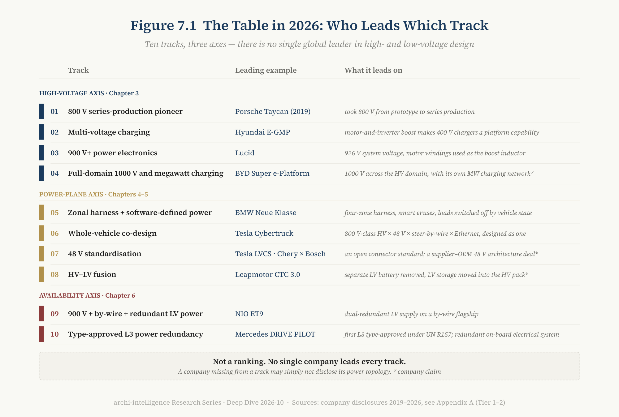
Figure 7.1 — Who leads which track. Reading note: the ten tracks are grouped by this article’s three axes — the high-voltage axis (Chapter 3), the power-plane axis (Chapters 4 and 5) and the availability axis (Chapter 6); each track lists only one leading example. It is not a ranking, nor a carmaker × track scoring matrix. A carmaker that does not appear may simply not have disclosed.
7.2 Tesla: what it leads is co-design, not voltage
Tesla is often taken to be “the leader” in this field. Split by track, that judgment holds only in part.
On high voltage and charging, Tesla was not the pioneer and does not lead. 800 V was first put into series production by Porsche in 2019; the Cybertruck’s high voltage is 700 V nominal, with a peak of 325 kW on North America’s fourth-generation Superchargers [T2], while megawatt-class charging has already been demonstrated in China on models from BYD, Zeekr and others [T2, company claim].
On low voltage and whole-vehicle co-design, Tesla’s lead is real. The Cybertruck is the first production vehicle to raise 48 V from “an auxiliary voltage for the powertrain” to “the vehicle’s main low-voltage architecture”, designed together with steer-by-wire and Ethernet; LVCS then turned that into an interface standard open to all.
But the lead is still demonstrative. As of this article’s data date, Tesla’s production vehicles with vehicle-wide 48 V are only the Cybertruck and the Cybercab; the Model 3 / Y still use a 16 V lithium low-voltage system [T2–T3]. [inference] What Tesla leads is not any voltage number but an architectural philosophy: optimizing high voltage, low voltage, by-wire, network and central compute as one system.
7.3 Three architecture archetypes
Gather the ten tracks once more and three architecture archetypes appear [inference]:
- High-voltage performance optimizers: focus on 800 / 900 / 1000 V, charging, efficiency and power density. Porsche, Lucid and BYD are representative.
- Charging-compatibility integrators: focus on seamless compatibility across chargers of different voltages, and on bidirectional charging. Hyundai and Lucid are representative.
- Whole-vehicle power / E/E co-designers: focus on designing high voltage, low voltage, zones, by-wire and network together. Tesla and NIO are representative; BMW Neue Klasse and Leapmotor’s next-generation platform are the ones to watch.
The three archetypes are not mutually exclusive; a carmaker can straddle two. But they answer different questions: the first two optimize one axis, high voltage; the third optimizes the relationships among the four planes. This article’s fourth-plane and availability theses are mainly about the third.
7.4 A caution about this table
This chapter deliberately gives no scores. The reason is stated in the editorial note: power topology is the least disclosed part of a vehicle. Mercedes-Benz looks “clearest” in 6.5 partly because it had to file safety reports for L3 type approval and for permits in US states; NIO is clearer than other Chinese carmakers because it chose to explain its digital architecture in detail at launch. [inference] A carmaker that appears little in this chapter may simply say little.
8. Supply Chain: 800 V enters a price war, 48 V is stuck on its ecosystem
8.1 800 V: from “is it available” to “is it worth it”
By 2026 the bottleneck of 800 V is no longer “are the parts available” but cost, scale and the utilization of charging infrastructure.
Silicon carbide is the key device of 800 V and the clearest reading of this supply chain’s maturity. According to TrendForce, global revenue from N-type silicon-carbide substrates was about USD 1.04 billion in 2024, down 9% year on year; Wolfspeed held 33.7%, TankeBlue 17.3% and SICC 17.1% [T2]. According to Yole, by 2025 Chinese companies held close to 40% of the silicon-carbide substrate market (about 10% in 2021), and silicon-carbide wafer prices fell by about 30% in 2024 [T2]. Wolfspeed, once the industry leader, filed for a prepackaged Chapter 11 restructuring on June 30, 2025 and emerged on September 29, cutting about USD 4.6 billion of debt [T1].
[inference] When the leader of a supply chain must go through bankruptcy restructuring to cope with price pressure, the chain’s problem is no longer technical maturity but overcapacity and margins. The risk of 800 V is shifting from engineering to geopolitics and finance.
On the demand side, 800 V penetration in China is still early: institutional estimates of the share of 800 V models in China’s 2024 new-energy passenger cars range from 7% to 8% [T3].
8.2 48 V: the parts are mature, the ecosystem is not
48 V is almost the opposite [inference]. Its core parts — 48 V batteries, DC-DCs, MOSFETs, smart eFuses, connectors — can all be bought, many of them in production since the mild-hybrid era. Zonal reference designs from Texas Instruments, Infineon and other chipmakers (see 4.3) show that the supply chain is ready.
But a reference design is not series production. What is really missing are the hundreds of endpoints of 3.5: window motors, door locks, lamps, pumps, fans. Their suppliers must develop new parts for a market that has not yet reached scale — a classic chicken-and-egg problem. The responses differ: Tesla wrote an open standard and invited everyone in; Hyundai has reportedly chosen to build its own system to protect its suppliers [T3]; Chery and Bosch chose joint development [T2]. Third-party research estimates that the inflection point for 48 V architectures is around 2028 [T3].
800 V: the parts are mature and scale has arrived. 48 V: the parts are mature, the ecosystem has not.
8.3 A comparison: the data center’s reverse migration
Box | The same physical problem in two industries
The car is not the first industry to hit the “low voltage, high current” problem. Hyperscale data centers walked the same road long ago: the Open Compute Project (OCP) has used a 48 V rack bus for years, converting again close to the load inside the server.
More interesting is what happened in 2025–2026. OCP’s “Mt. Diablo” (Diablo 400) specification, drafted jointly by Microsoft, Meta and Google, pushes rack power from 48 V DC to ±400 V DC to support AI loads of 100 kW to 1 MW per rack; OCP states explicitly that 400 V was chosen as the nominal voltage in order to borrow the supply chain already built by electric vehicles, gaining economies of scale, mature quality and more efficient manufacturing [T1–T2]. NVIDIA has proposed an 800 V DC data-center architecture [T3].
[inference] This is neither “cars copying servers” nor “servers copying cars” but an infrastructure convergence of two industries on the same power-density problem — and by 2026 the technology transfer runs both ways: cars borrowed 48 V from the data center, and the data center is borrowing 400 / 800 V from cars. It is one more appearance, in power, of the two-layer model proposed in D1: the infrastructure layer converges across industries.
9. One Line, Three Governance Regimes
9.1 Physical convergence
Chapter 1 noted that the 60 V line has almost no disagreement worldwide: UN R100, GTR 20, ISO 6469-3 and China’s GB 18384-2025 draw it in the same place, and China’s new national standard explicitly aims at harmonization [T1–T2]. There is no physical difference between a “European 800 V” and a “Chinese 800 V”.
The differences lie above and below the line: who approves, what is tested, how strictly, and who sets the interfaces.
9.2 China: mandatory standards that accelerate, system-level standards that lead
In 2026 China put in place a dense set of mandatory national standards related to electric power:
- July 1, 2026: two mandatory standards took effect on the same day. GB 18384-2025 works at vehicle level, adding the physical one-touch cut-off (see 5.5), an underbody impact test (a 150 mm-diameter hemispherical barrier striking the underside of the pack at 35 km/h), and safety-function requirements such as warnings for power reduction, low charge and thermal faults; already-approved vehicle types have a transition until July 1, 2027 [T1–T2]. GB 38031-2025 works at battery level, requiring thermal propagation to cause “no fire, no explosion” [T1–T2].
- A system-level high-voltage connection standard. GB/T 37133-2025, High-voltage connection systems for electric vehicles, was issued and took effect on February 28, 2025, replacing the 2018 standard on “high-voltage, high-current harnesses and connectors”; its drafters include Huawei Digital Power, BYD, CATL, Xiaomi, Great Wall, Geely, TE Connectivity, Amphenol and Rosenberger; a foreign-language edition was published in April 2026 [T1]. The project note for the foreign-language edition states that there is currently no IEC / ISO-level standard for on-board high-voltage connection systems abroad — German practice mainly refers to the industry consortium standard LV214, US practice to USCAR-2 / USCAR-37, and Japanese practice to carmakers’ own standards — so “it is necessary to produce a foreign-language edition and promote the Chinese approach” [T1]. This is the standard-setter’s own account; this article has not independently checked the claim that “no system-level standard exists abroad”.
- Automated driving. GB 44721-2026 takes effect on July 1, 2027 (see 6.6) [T1–T2].
[inference] China’s distinctive feature is that vehicles, batteries, connectors, chargers and grid-side equipment can co-evolve at great speed in one huge unified market, and national standards are the synchronizer of that co-evolution. This is also the structural reason China’s “voltage race” is more aggressive than elsewhere.
9.3 Europe: type approval and a functional-safety culture
Europe’s system is type approval under UN regulations (R100, R157, R155, R156), plus ISO engineering standards, plus supply specifications jointly written by German carmakers (for 48 V, LV148, which later grew into VDA 320 and ISO 21780) [T1–T2]. D2’s data show European carmakers leading the world on the functional-safety dimension [T1, this series’ published research]; Mercedes-Benz was the world’s first carmaker to obtain L3 type approval under UN R157.
Europe’s new constraint is on the data side: the EU Battery Regulation (EU) 2023/1542 requires electric-vehicle batteries placed on the EU market to carry a battery passport, with an application date commonly cited as February 18, 2027 [T2]. This turns the data chain from the battery management system to the cloud into an object of compliance too.
9.4 United States: federal standards and self-certification
The US path is Federal Motor Vehicle Safety Standards plus self-certification rather than type approval. FMVSS 305 has evolved into FMVSS 305a: the final rule was published on December 20, 2024, harmonizes with GTR 20, adds requirements on battery-system safety and emergency-response information, and becomes mandatory from September 1, 2027 [T1–T2]. The charging interface in North America has unified on SAE J3400 (derived from Tesla’s NACS), and in 2025 J3400/2 standardized the connector up to 1000 V [T2].
9.5 Charging interfaces: the most divided place above the line
If vehicle electrical safety is converging, the charging interface is where the three regions diverge most: China’s GB/T 2015 and its upgrades plus ChaoJi, Europe’s CCS2, North America’s J3400, and the Megawatt Charging System (MCS) for heavy trucks. China’s megawatt-class passenger-car charging is led by carmakers and arrived ahead of standards, with some solutions needing two plugs; Europe follows a standards-first, operator-led path; the US unified the interface first and is adding 1000 V afterwards [inference, combining T1–T2 sources]. Models for global markets need multi-region variants of the charging inlet, communication protocol and boost compatibility.
9.6 Summary
E6 (governance) | The same 60 V physical boundary has grown three governance regimes in three regions: China accelerates through mandatory standards and leads with system-level standards; Europe’s strength is type approval and a functional-safety culture; the United States relies on federal standards plus self-certification, and has unified the charging interface.
This matches D1’s two-layer convergence–divergence model exactly: the physical boundary converges; the ways of governing it diverge.
10. Putting the Knife to Our Own Throat: counter-arguments and revision triggers
10.1 Seven counter-arguments
Counter-argument 1: power is an engineering detail, not an architecture question. Response: In the era of 12 V plus mechanical backups, that held (4.1). By-wire removed the mechanical backup, zoning broke the organizational split, and 48 V broke “the same electricity”. Once all three premises are gone, the power topology is the functional-availability topology (Chapter 6).
Counter-argument 2: 48 V is a Tesla one-off; the industry will not follow. Response: As of this article’s data date, Ford, Leapmotor and Chery (with Bosch) have all announced vehicle-wide 48 V platforms with production around 2027; but these are still plans. This article’s judgment on 48 V is “direction settled, pace not”, and it lists the pace as a revision trigger (10.2, item 2).
Counter-argument 3: high-power actuators will hang directly on high voltage and bypass 48 V. Response: The Li Auto L9 Livis’s 800 V active suspension is a real counter-example (3.6). This article’s judgment is that whether high-power chassis actuators sit on 48 V or on high voltage is still an open question; if “directly on high voltage” becomes mainstream, the value space of 48 V shrinks to medium-power loads. This is also listed as a revision trigger.
Counter-argument 4: redundancy is too expensive; L4 fleets will replace hardware redundancy with operational measures. Response: Remote assistance, speed limits and narrower operating domains can indeed reduce the need for some hardware redundancy. But they reduce “how much MESS is needed”, not “whether MESS is needed” — as long as no human aboard is the fallback, there must always be energy after a fault to bring the car to a safe state.
Counter-argument 5: integrating low voltage into the high-voltage pack is a better trade-off than a separate small battery. Response: On the distribution ledger that is quite likely true; on the availability ledger, it must show that the low-voltage part in the pack has no common-cause failure with the main energy source (6.7). This article does not judge which is better; it only argues that the two ledgers must be kept separately.
Counter-argument 6: “the fourth plane” is yet another framework. Response: The fourth plane is not a maturity ladder; it defines no levels and gives no scores. It is an analytical view with a single purpose: to make power visible in architecture reviews. It conflicts neither with D2’s five-dimension scoring nor with September’s S0–S5 stack model (4.2).
Counter-argument 7: megawatt charging means nothing to ordinary users; the voltage race is just marketing. Response: This counter-argument has considerable merit. Peak charging power depends on dedicated chargers, battery temperature and a narrow state-of-charge window, and its meaning for everyday use is limited. That is also why this article deliberately avoids a “voltage league table” and asks about full-domain HV penetration instead (3.3).
10.2 Six revision triggers
If any of the following occurs, the corresponding thesis of this article must be revised:
| # | Trigger event | Thesis revised |
|---|---|---|
| 1 | A zonal production platform pulls power distribution back into a central distribution box in its next-generation model | E2 |
| 2 | Ford UEV and Leapmotor LEAP 5.0 reach production on schedule in 2027 with 48 V, and at least two more carmakers put vehicle-wide 48 V platforms into production by the end of 2028 | the “moves more slowly” pace judgment in E3 |
| 3 | ”High-power actuators directly on high voltage” becomes the mainstream solution for new platforms | E3’s judgment on the value space of 48 V |
| 4 | A production L3 or L4 model obtains type approval or market access with a single-path low-voltage supply | E4 |
| 5 | A major regulation or standard begins to set explicit quantitative requirements for the energy budget after a fault | the judgment in 6.6 that “MESS is the missing number” |
| 6 | ISO or IEC publishes a system-level standard for on-board high-voltage connection systems | the judgment in 9.2 that “China leads with system-level standards” |
11. Conclusion: three judgments and one warning
Back to the title. Muscle and nerve is not a figure of speech — it is the most accurate description of the relationship between high and low voltage: at runtime, the muscle feeds the nerve; at start-up, the nerve wakes the muscle; and in the by-wire era, damage to the nerve means the car can no longer be controlled.
Judgment one: electricity has turned from infrastructure into part of the function. So the E/E architecture needs a fourth plane. A zonal architecture that has zoned only its data is only half done; the zonal controller is becoming an edge node that combines data, control and power — thinner in logic, thicker in power. To judge how far a vehicle’s zoning has gone, the question is not “how many zonal controllers”, but “have distribution, fault isolation and energy sources been zoned too”.
Judgment two: distribution is not availability, and the last number of availability is energy. Efficiency and resilience are two independent axes. The essence of redundancy is independence, not duplicated parts; logical redundancy is not physical independence. Regulations have begun to specify what a vehicle must do after a fault, but not how much energy it is guaranteed to have to do it — a number we call the Minimum Energy to Safe State.
Judgment three: 800 V is a vertical migration, 48 V a horizontal one; what wins 48 V is the contract, not the voltage. The 800 V supply chain has entered a price war, and its problems have become cost and geopolitics; the parts for 48 V are mature, and its problem is hundreds of endpoints and the interfaces of an entire supply chain. Whoever’s connectors, voltage windows and isolation rules enough suppliers adopt will set the cost curve of 48 V.
One warning: do not mistake a voltage number for an architecture. 400 V, 800 V, 1000 V, 12 V, 48 V are architecture classes, not readings, and certainly not rankings. The higher the voltage, the more returns diminish and costs rise; the more “advanced” 48 V gets, the more it must answer whether it holds up after a fault. What defines a car is not how high its voltage is, but in what topology electricity reaches every place that needs it — and whether it still gets there when something goes wrong.
Software can manage all of this, but the last gate is still physical.
Appendix A | Evidence grades and main sources
A.1 Evidence grades
| Mark | Meaning |
|---|---|
| [T1] | Official primary sources: regulation and standard texts and official registers, official technical documents and press releases from carmakers and suppliers, official owner’s / service manuals, regulatory filings |
| [T2] | Official launch events, official blogs and reliable independent reporting; includes company claims, marked “company claim” in the text |
| [T3] | Media reports, secondary analysis and research-firm estimates, not confirmed against primary sources |
| [inference] | The author’s judgment, not a statement of fact |
Note: All future dates (Ford UEV 2027, Leapmotor LEAP 5.0 2027, BorgWarner 2029, FMVSS 305a 2027-09-01, GB 44721-2026 2027-07-01, etc.) are plans or effective dates, not facts that have occurred. Reference designs (Texas Instruments, Infineon) show only that the supply chain is ready, not that they are in vehicles.
A.2 Main sources (by chapter)
Chapter 1
- UN R100 Rev.3 — https://unece.org/sites/default/files/2024-01/R0100r3e.pdf
- GB 18384-2025 (national standard full-text disclosure system) — https://openstd.samr.gov.cn/bzgk/std/newGbInfo?hcno=36F2726143479B33E76BACB6BD2AF4B0 ; SESEC on harmonization with R100 / GTR 20 / ISO 6469-3 — https://sesec.eu/?p=7358
- ISO 21780:2020 (confirmed at review 2026-06-29) — https://www.iso.org/standard/71607.html ; sample — https://cdn.standards.iteh.ai/samples/71607/9d608ba9e8414f02a19e68176c1660ac/ISO-21780-2020.pdf
- Tesla Cybertruck Owner’s Manual: Subsystems (700 V nominal, 48 V 4 Ah) — https://www.tesla.com/ownersmanual/cybertruck/en_us/GUID-32CD64C8-5661-45A8-BFB6-35603858F7FB.html
- Tesla Cybertruck Service Manual: MV Battery (“mid voltage”) — https://service.tesla.com/docs/Cybertruck/ServiceManual/en-us/GUID-F6BB141A-3615-41DE-A7C7-4DDF405C9C21.html
Chapter 2
- Tesla Cybertruck Owner’s Manual: Electric Vehicle Components — https://www.tesla.com/ownersmanual/cybertruck/en_us/GUID-2233D4D1-D4E5-4897-9A41-DE8593381CAA.html ; Instructions for Transporters — https://www.tesla.com/ownersmanual/cybertruck/en_us/GUID-17ABBF87-8EB4-4FFC-8D79-B9FF53F7916D.html
- BorgWarner, 2026-02-11 — https://www.borgwarner.com/newsroom/press-releases/2026/02/11/borgwarner-set-to-deliver-power-packed-integrated-drive-module-and-generator-module-with-dual-inverter-to-major-north-american-oem
- Leapmotor technology day (CTC 3.0): Gelonghui — https://m.gelonghui.com/news/5322459 ; The EV Report — https://theevreport.com/leapmotor-leap-5-0-architecture-ctc-3-0-battery ; Huxiu (repair-cost concerns, T3) — https://www.huxiu.com/article/4890949.html
Chapter 3
- Aptiv, How to Make the Leap to 48V Electrical Architectures — https://www.aptiv.com/en/insights/article/how-to-make-the-leap-to-48v-electrical-architectures
- Hyundai E-GMP — https://www.hyundai.com/worldwide/en/newsroom/detail/0000000812
- NIO ET9 official page — https://www.nio.com/et9
- BYD Super e-Platform — https://byd.com/mea/news-list/byd-unveils-super-e-platform-with-megawatt-flash-charging?amp=&=
- Lucid Gravity (WardsAuto) — https://www.wardsauto.com/news/why-lucid-gravity-charges-past-tesla-even-at-tesla-chargers/778665/
- Tesla, Standardizing Automotive Connectivity (LVCS, 2024-10-27) — https://www.tesla.com/en_hk/blog/standardizing-automotive-connectivity
- Ford UEV (From The Road) — https://www.fromtheroad.ford.com/us/en/articles/2026/ford-electric-vehicle-platform-battery-efficiency ; SAE Mobility Engineering — https://saemobilus.sae.org/articles/ford-announces-48-volt-architecture-future-electric-truck-26autp04_10
- Chery × Bosch 48 V architecture (Gasgoo) — https://autonews.gasgoo.com/articles/market-industry/bosch-chery-deepen-cooperation-leading-mass-production-of-48v-vehicle-architectures-2048740519755198465
- Leapmotor LEAP 5.0 (Stockstar, reposting the official release) — https://wap.stockstar.com/detail/IG2026091700003939
- Hyundai 48 V (Notebookcheck, T3) — https://www.notebookcheck.net/Hyundai-to-challenge-Tesla-with-48V-system-upgrade-for-all-its-cars-and-Boston-Dynamics-robots.1059617.0.html
- NIO ET9 digital architecture (IT Home) — https://www.ithome.com/0/817/972.htm
- Li Auto L9 Livis (KrASIA) — https://kr-asia.com/li-auto-uses-the-li-l9-livis-to-make-its-case-as-a-technology-company
Chapter 4
- BMW Group, Four “Superbrains” for the Neue Klasse — https://www.bmwgroup.com/en/news/general/2025/superbrains.html
- NIO ET9 digital architecture (Gasgoo) — https://autonews.gasgoo.com/articles/news/nio-introduces-et9-models-advanced-digital-architecture-70035454
- TI TIDA-020094 — https://www.ti.com/tool/TIDA-020094
- GM central computing platform (zonal aggregators) — https://news.gm.com/home.detail.html/Pages/news/us/en/2025/oct/1022-SDV-GM-centralized-vehicle-computer-platform-electric-gas-vehicles.html
Chapter 5
- GB 18384-2025 key points (The Paper) — https://m.thepaper.cn/newsDetail_forward_33458192 ; ArenaEV — https://m.arenaev.com/china_overhauls_ev_regulations_with_tough_mandatory_fire_safety_standards-amp-5983.php
Chapter 6
- SAE J3016-2026 (ANSI Webstore) — https://webstore.ansi.org/standards/sae/sae30162026
- Mercedes-Benz DRIVE PILOT VSSA — https://group.mercedes-benz.com/dokumente/innovation/sonstiges/2023-03-06-vssa-mercedes-benz-drive-pilot.pdf ; redundant architecture (Automotive World, reposting the official release) — https://www.automotiveworld.com/news-releases/mercedes-benz-backs-redundancy-for-safe-conditionally-automated-driving ; US launch release (Automotive Fleet) — https://www.automotive-fleet.com/10207114/mercedes-benz-announces-automated-driving-system-drive-pilot
- Waymo Safety Framework (2020) — https://waymo.com/blog/2020/10/sharing-our-safety-framework/
- GB 44721-2026 (Xinhua) — https://www.news.cn/politics/20260804/b872e55762d9456080314e506299e4b6/c.html ; National Business Daily (ADS GTR) — https://www.mrjjxw.com/articles/2026-08-04/4531747.html
- China’s first L3 vehicles (CnEVPost) — https://cnevpost.com/2025/12/23/arcfox-deepal-secure-1st-dedicated-license-plates-l3/
Chapter 7
- Porsche Taycan 800 V — https://newsroom.porsche.com/en/products/taycan/glossary-18550.html
- Tesla V4 Supercharger 325 kW (electrive, 2025-01-29) — https://www.electrive.com/2025/01/29/tesla-increases-to-325-kw-in-north-america-for-the-v4-supercharger
Chapter 8
- TrendForce SiC substrates (Semiconductor Today) — https://www.semiconductor-today.com/news_items/2025/may/trendforce-120525.shtml
- Yole, Wolfspeed and SiC competition — https://www.yolegroup.com/strategy-insights/wolfspeeds-bold-sic-bets-meet-tough-timing-and-growing-competition/
- Wolfspeed 8-K (SEC) — https://www.sec.gov/Archives/edgar/data/895419/000089541925000060/exhibit99_1050825.htm
- 800 V penetration: Zuosi Auto Research (Tencent News) — https://news.qq.com/rain/a/20250729A02BM600 ; Sina Tech — https://finance.sina.com.cn/tech/roll/2025-05-22/doc-inexiceh8106739.shtml
- ResearchInChina 48V PDN 2025 (BusinessWire) — https://www.businesswire.com/news/home/20250617989801/en/
- OCP, Mt Diablo (Diablo 400) — https://www.opencompute.org/index.php/blog/major-contributions-advance-ocp-open-systems-for-ai-at-apac-summit
Chapter 9
- GB/T 37133-2025 — https://std.samr.gov.cn/gb/search/gbDetailed?id=2FF37940EB8DD753E06397BE0A0A413F ; foreign-language edition project note — https://std.samr.gov.cn/gfs/search/gfsDetailed?id=F159159B67EA0802E05397BE0A0A5F89
- GB 38031-2025 / GB 18384-2025 in force (electrive) — https://www.electrive.com/2026/07/01/stricter-ev-and-battery-standards-take-effect-in-china/
- FMVSS 305a final rule summary — https://jjkellercompliancenetwork.com/news/nhtsa-final-rule-federal-motor-vehicle-safety-standards-fmvss-no-305a-electric-powered-vehicles-electric-powertrain-integrity-global-technical-regulation-no-20-incorporat
- SAE J3400/2 (EE Power) — https://eepower.com/tech-insights/sae-j3400-2-sets-the-stage-for-quicker-smarter-nacs-charging/
- EU Battery Regulation (EU) 2023/1542 (EUR-Lex) — https://eur-lex.europa.eu/eli/reg/2023/1542
Published research in this series
- D1 (2026-01), D2 (2026-02), D3 (2026-03), D4 (2026-04); Deep Dive 2026-08 The Driver Exits; Deep Dive 2026-09 A System of Operating Systems.
Appendix B | Concepts introduced and adopted
| Concept | Status | Definition |
|---|---|---|
| The fourth plane | introduced here | the power plane: how energy is distributed, converted and isolated, and how it is reconfigured after a fault. A peer of the compute, network and software planes. An analytical view, not a scoring dimension or maturity ladder |
| Distribution ≠ availability | introduced here | distribution architecture answers “how does electricity get there”; availability architecture answers “after a fault, is there still power, and for how long”. The two are independent axes |
| Full-domain HV penetration | introduced here | the share of components in the vehicle’s high-voltage domain that run natively at a given voltage class. For now a way of asking, not a quantifiable metric |
| MESS (Minimum Energy to Safe State) | introduced here | the minimum energy the system must be able to guarantee, from the moment a power fault is detected until the vehicle has reached and is holding a minimal risk condition, up to handover to rescue or remote assistance |
| Software-defined power | adopted (already used in data centers); defined here in the automotive E/E context | the allocation, protection and priority of electric power are decided dynamically by software according to vehicle state, rather than fixed once by hardware at design time |
| Power-Zonal | term | distribution, voltage conversion and fault isolation organized by physical zone and handled by the zonal controller |
| Independence chain | this article’s analytical frame | six layers of power redundancy: energy, conversion, distribution, compute and network, actuation, energy management |
Relationship to this series’ existing frameworks: none of the concepts above revises any published conclusion of D1–D4, changes D2’s five-dimension scoring or AR mapping, or constitutes a new maturity ladder. The fourth plane interfaces with S0 (the E/E physical substrate) of Deep Dive 2026-09 and with D4 (functional safety) of D2; see 4.2.
Appendix C | Abbreviations
| Abbreviation | Full form / meaning |
|---|---|
| ADS GTR | UN Global Technical Regulation on automated driving systems |
| AR0–AR5 | Architecture Readiness, this series’ architecture-readiness ladder |
| ASIL | Automotive Safety Integrity Level |
| CTC | Cell to Chassis |
| DC-DC | DC-to-DC converter |
| eFuse | electronic fuse |
| FMVSS | Federal Motor Vehicle Safety Standards (US) |
| GTR 20 | UN Global Technical Regulation No. 20 (electric vehicle safety) |
| HV / LV | High Voltage / Low Voltage |
| LVCS | Low-Voltage Connector Standard (Tesla) |
| MCS | Megawatt Charging System |
| MESS | Minimum Energy to Safe State (introduced here) |
| MRM | Minimum Risk Manoeuvre |
| MV | Mid Voltage, Tesla’s service term for the Cybertruck’s 48 V system |
| OCP | Open Compute Project |
| OTA | Over-the-Air update |
| PoL | Point of Load |
| SiC | Silicon carbide |
| ZCU | Zonal Control Unit |
A revisable observation, not a locked claim — its revision triggers are stated within. Not investment advice.